Designing a PCB
learning KiCAD and keyboard design

As with many of my random projects, this was inspired by a truly frustrating experience I had with a keyboard called the Gentleman65. Amid other problems, the firmware provided for that board was poorly written, and wouldn’t compile so I took it upon myself to rewrite it. Well it was more problems than it was worth and I ended up selling it off, but I was curious to see if I could have done a better job of designing a PCB than the maker had. I came in with a little tinkering and soldering experience and not much else, but with the power of the internet and a fellow PCB designer in Sweden, I decided to jump in and give it a go.


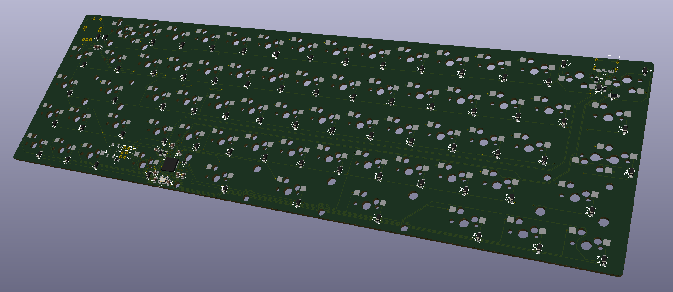
I started by creating a matrix which places all the switches in their approximate locations. This allows me to use fewer pins on the MCU but still have the same number of keys as a 65% keyboard would. This was perhaps the easiest part of the design because all it involves is connecting things that should be connected. The hard part comes in arranging all the components on the board and ensuring that all connections are done in a manner that you don’t break important PCB rules. Even so, it’s not that bad.

The PCB design portion is actually fairly straightforward if you aren’t aiming to go beyond just mechanical switches on a board. In this iteration, I opted to throw in a rotary encoder which necessitated an extra two MCU pins, but there is more fun stuff you can add such as OLED displays, e-ink displays, touch sliders, and LEDs.
I tried to autoroute this PCB, but it wasn’t very clean obviously. The problems you may have with high performance PCBs used in industry (differential pair spacing, routing over power lines, trace angles etc.) aren’t really a concern so you could botch it and it would likely still work. I rerouted that MCU area probably 5 or 6 times before settling on the spaghetti mess in the picture above. It’s good enough that I’m ready to send it for prototypes, but I would redo all the wiring again if I ever tried to make some for friends.
The next step is to order a few prototypes and make sure that it functions properly, so be prepared for a part 2 soon…